Two Essential Engineering Documents
In wastewater treatment plant design, the Process Flow Diagram (PFD) and the Piping & Instrumentation Diagram (P&ID) are the two most fundamental engineering drawings. They are often confused because they both describe the same plant — but at very different levels of detail. Understanding what each document contains, and when it is produced, is essential for anyone commissioning, reviewing, or building a treatment facility.
What a PFD Contains
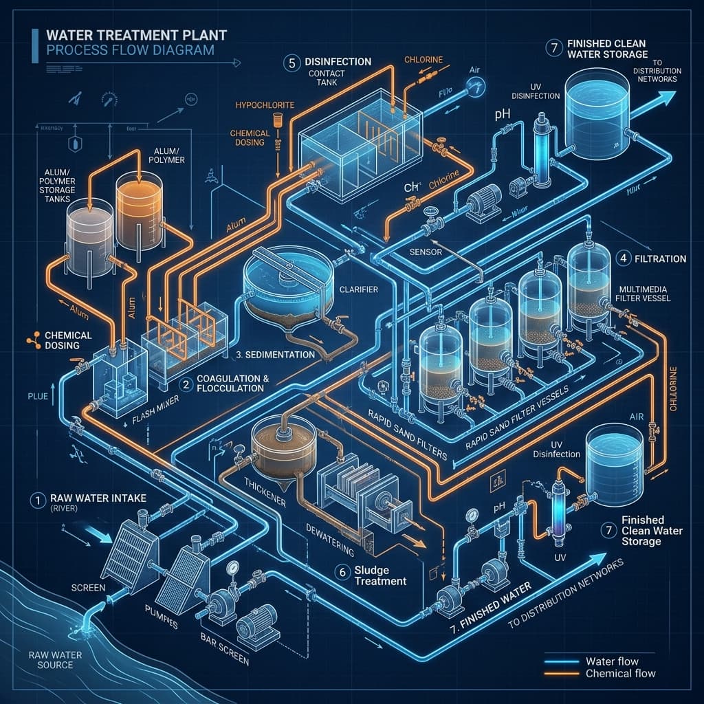
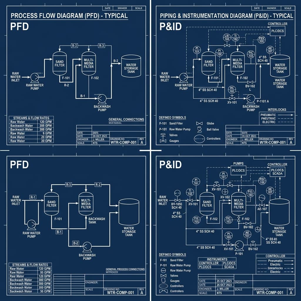
A PFD is the process-level design document. It shows the sequence of treatment stages (such as screening → equalization → biological treatment → clarification → disinfection), the flow of water and sludge between stages, and key process parameters such as flow rates, tank capacities, and recycle ratios. It does not show individual pipe sizes, valve types, or instruments. The PFD is produced early in the design sequence — during FEED — and forms the basis for process design calculations and equipment sizing.
What a P&ID Contains
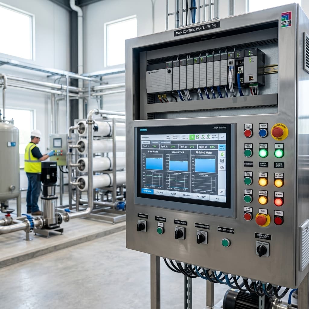
A P&ID is the detailed engineering document that builds on the PFD. It shows every pipe, valve, pump, instrument, and control loop in the plant. Each instrument has a tag number following ISA-5.1 conventions (e.g., FT-101 for a flow transmitter). Control loops are drawn showing the relationship between sensors, controllers, and final control elements. Every equipment item has a tag, size, and material specification. The P&ID is used by procurement engineers, construction teams, and operations staff — it is the definitive reference for how the plant is built and operated.
Design Sequence: PFD Comes First
The correct engineering sequence is always PFD before P&ID. You cannot produce a meaningful P&ID without first validating the process via the PFD. The PFD establishes what unit operations exist and what flows through each; the P&ID then specifies exactly how each unit is piped and controlled. Skipping the PFD and going straight to a P&ID is a common mistake on smaller projects that leads to costly rework during detailed design.
When SMRS Infra Delivers Each Document
SMRS Infra delivers PFDs as part of our Process Design Calculations service, typically at the pre-FEED or FEED stage. P&IDs are produced as part of our Engineering Drawings service, after the PFD has been reviewed and approved. Both documents are produced in AutoCAD to international standards and are supplied as PDF and DWG files. If you are unsure which document you need for your current project stage, contact us — we will advise based on your specific requirements.
Need engineering support for your project?
SMRS Infra provides process design calculations, P&ID packages, and PLC automation engineering for water and wastewater treatment plants.
Get in Touch