What is a Process Flow Diagram?
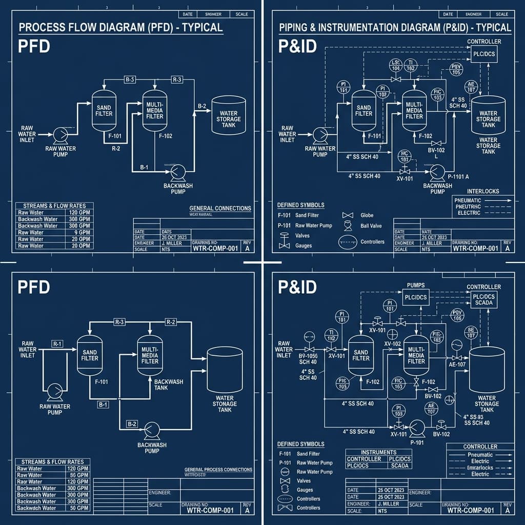
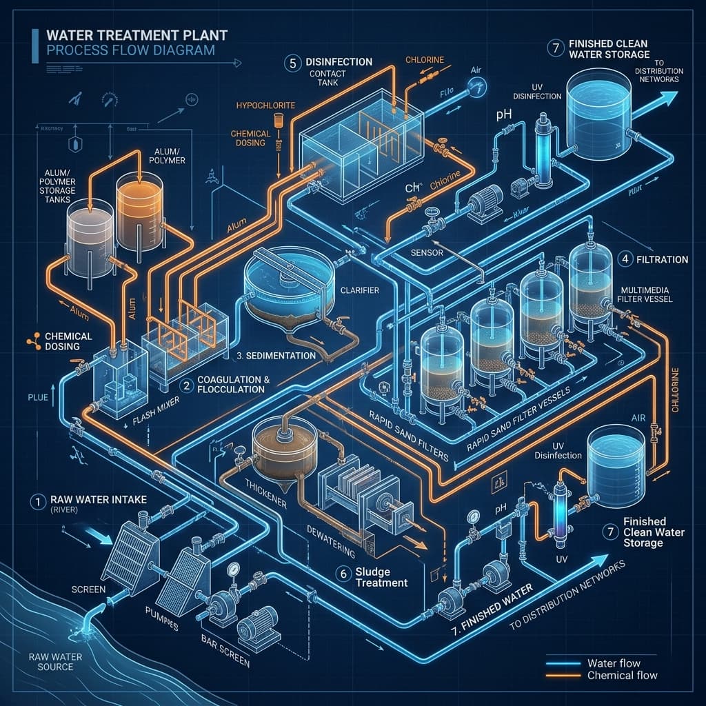
A Process Flow Diagram (PFD) is a schematic drawing that illustrates the sequence of chemical, physical, and biological processes in a water or wastewater treatment plant. It shows every major unit operation — from raw water intake through to treated effluent discharge — along with the flow paths connecting them. Unlike a P&ID, a PFD focuses on the process logic rather than mechanical detail, making it the starting point for any plant design.
Key Elements of a Water Treatment PFD
A well-prepared water treatment PFD includes: (1) Unit operation blocks representing each treatment stage (screening, coagulation, biological treatment, filtration, disinfection, sludge handling); (2) Process flow lines showing the direction of water and chemical movement; (3) Key design parameters such as flow rates, treatment capacities, and recycle streams; (4) Chemical dosing points for coagulants, antiscalants, pH adjusters, and disinfectants; (5) Sludge and waste streams. Together, these elements give engineers and clients a complete picture of how the plant will operate before any detailed engineering begins.
PFD vs P&ID — A Common Confusion
Engineers frequently ask about the difference between a PFD and a P&ID. A PFD is the process-level document: it shows what happens, not how every pipe and instrument is connected. A Piping & Instrumentation Diagram (P&ID) is the detailed engineering document that builds on the PFD, adding every pipe size, valve, instrument, control loop, and tie-in point. The PFD comes first in the design sequence; the P&ID follows once the process has been validated.
When Do You Need a PFD?
A PFD is required at the early stages of any water or wastewater treatment project — typically during the pre-FEED (Front-End Engineering and Design) or FEED phase. It is also essential for regulatory submissions, EPC tender packages, investment proposals, and design basis documentation. If you are extending an existing plant, the PFD is used to model the impact of the new unit operations on the overall process.
How SMRS Infra Prepares PFDs
At SMRS Infra, every PFD is developed from first principles. We begin with influent characterisation — understanding the raw water quality, flow rates, and discharge norms. We then select and size each treatment unit, calculate mass and hydraulic balances, and document all chemical dosing requirements. The final PFD is produced in AutoCAD and delivered as a PDF and native DWG file, ready for use in your detailed engineering or regulatory submission package.
Need engineering support for your project?
SMRS Infra provides process design calculations, P&ID packages, and PLC automation engineering for water and wastewater treatment plants.
Get in Touch